Underground Intelligence Bureau
Ask Scout
Handbook · The practical half

Depth Indication

Chapter 32 of 33 · printed page 22

Depth indication is to the centre of the magnetic field, not to the top of the buried utility.

Depth indication should not be attempted near to the Genny, signal clamp, connection, tee, bend or joint, or less than 25 metres away from the Genny when using induction.

Depth is indicated after a single press and release of the depth button (holding the button will activate Mouse depth and the letter 'M' will appear on the screen).

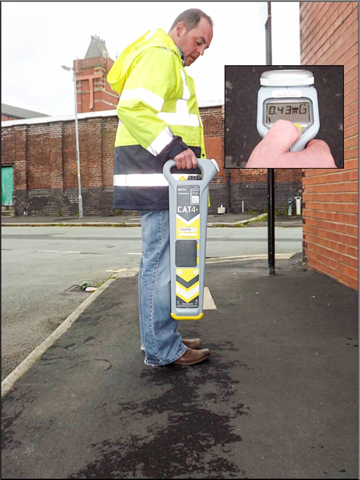
Depth accuracy can be checked by taking a depth at the centre of the service, checking in front and behind, and raising the CAT off the ground by a measured distance and rechecking that the new reading corresponds to the previous depth plus the distance raised. Remember this is still only a guide.

Always check the depth indication a few centimetres either side of the located position, and observe the shallowest reading.

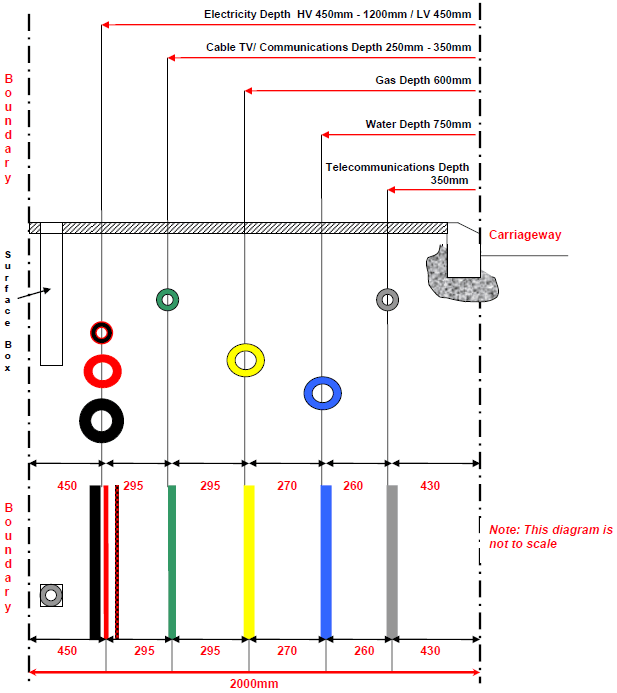
NJUG (National Joint Utilities Group) guidance recommends standard positioning of utility apparatus in a 2 metre footway — see the figure. The same positioning should apply in the carriageway/service strip (if safe and practical to do so) where a development has no footway available for services, or the boundary of the property is on the carriageway; refer to minimum depths in carriageways, and for further advice contact the asset owner.

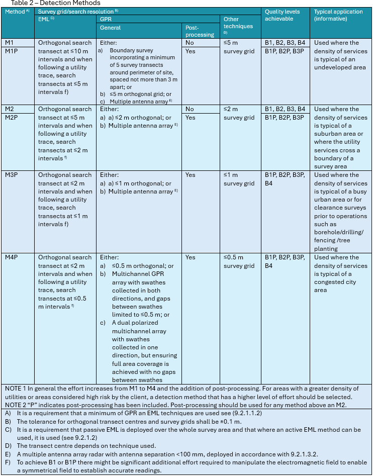
PAS128 survey types (from PAS128:2022): each survey is categorised by type, quality level (QL) and whether data has been post-processed. See the table figure for the full breakdown.

The figures

7 from the printed chapter
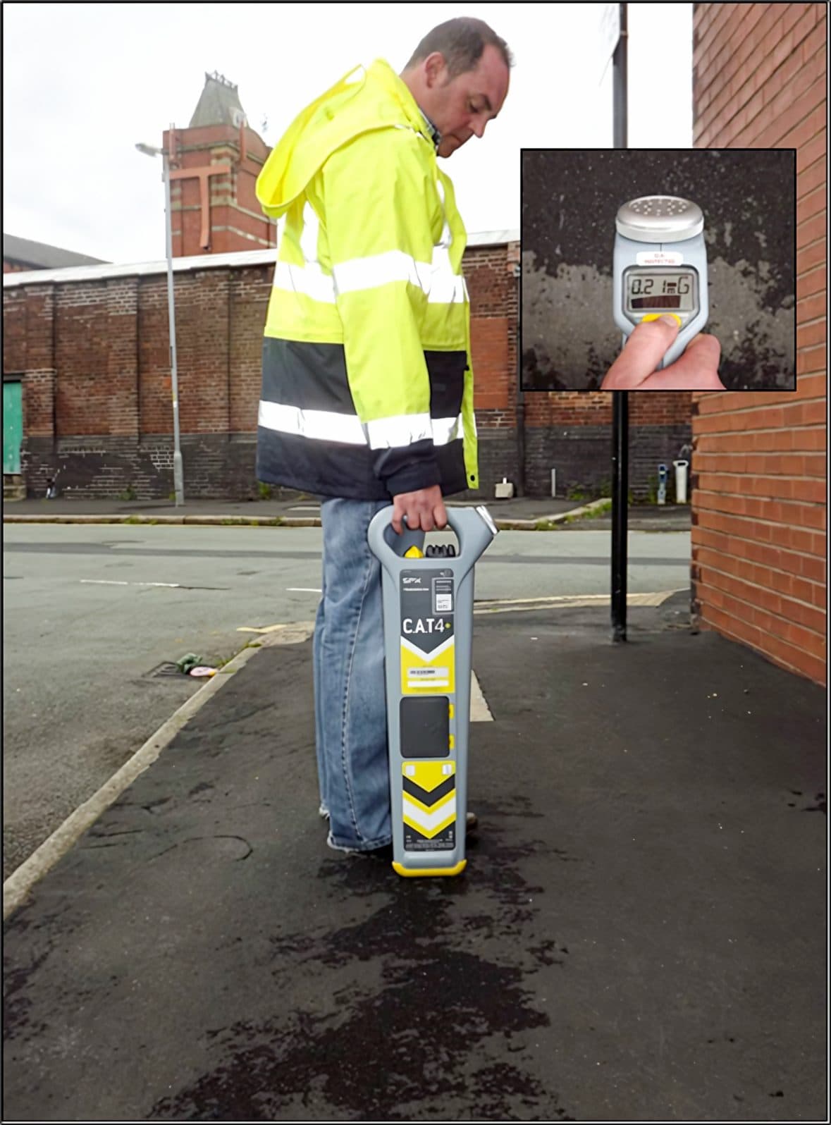
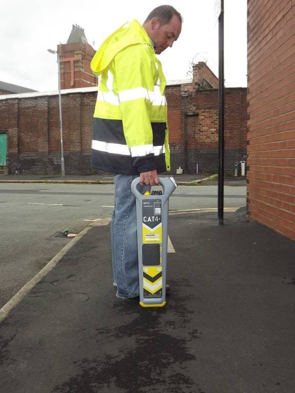
Operative holding the CAT4 vertical over the line, inset showing the depth button being pressed.
Fig 01Operative holding the CAT4 vertical over the line, inset showing the depth button being pressed.
Operative over the line with the inset display showing a depth reading of 0.43 m.
Fig 02Operative over the line with the inset display showing a depth reading of 0.43 m.
Operative with the CAT4 held vertical, directly over the traced line.
Fig 03Operative with the CAT4 held vertical, directly over the traced line.
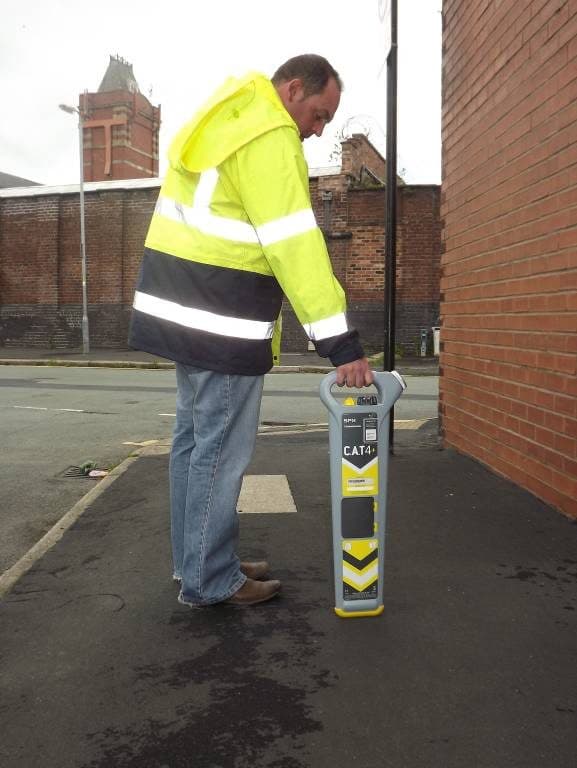
Operative holding the CAT4 vertical over the marked line, second angle.
Fig 04Operative holding the CAT4 vertical over the marked line, second angle.
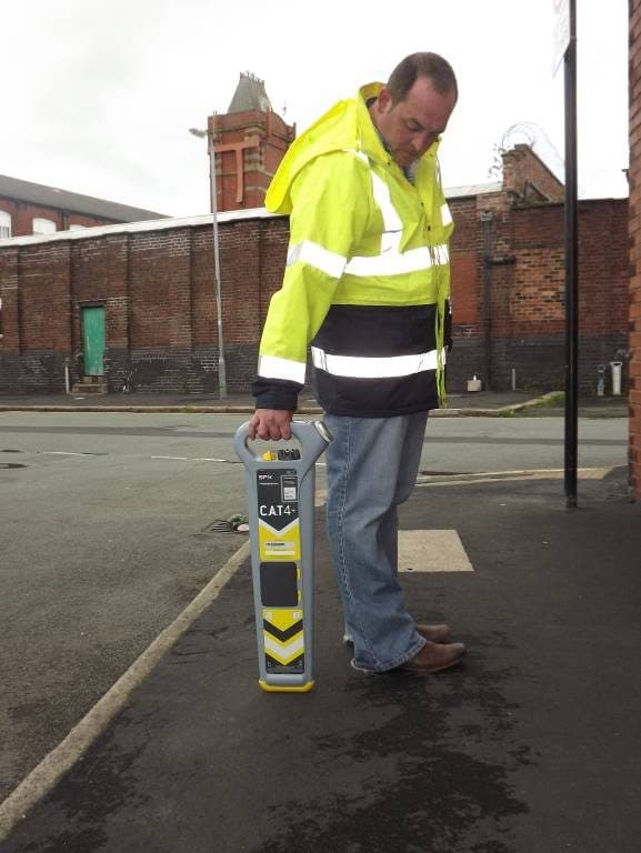
Operative following the traced line along the footway with the CAT4 held low.
Fig 05Operative following the traced line along the footway with the CAT4 held low.
Diagram of typical utility depths under a carriageway: electricity 450–1200 mm, cable TV and comms 250–350 mm, gas 600 mm, water 750 mm, telecoms 350 mm, with the colour-coded marker bars.
Fig 06Diagram of typical utility depths under a carriageway: electricity 450–1200 mm, cable TV and comms 250–350 mm, gas 600 mm, water 750 mm, telecoms 350 mm, with the colour-coded marker bars.
Table of detection methods M1 to M4P with survey grid resolutions, post-processing and quality levels.
Fig 07Table of detection methods M1 to M4P with survey grid resolutions, post-processing and quality levels.
Filed under